Instruments
Instrumentation Control Units
The instrumentation control unit (ICU) provides the driver with engine and vehicle information. It is comprised of standard and optional gauges, an audible warning, a driver message center, and a lightbar containing warning and indicator lamps (also known as telltales). Warning and indicator lamps illuminate in red (danger), amber (caution), green (status advisory), or blue (high-beam headlights activated).
Argosy vehicles are equipped with either an ICU4M ( Fig. 4.1 ), ICU3 ( Fig. 4.2 ), or ICU2M ( Fig. 4.3 ).
The following headings in this chapter provide additional information and operating instructions for ICU components:
"Warning and Indicator Lights"
"Instruments"
"Driver Message Center"

- 1. Engine Oil Pressure Gauge
- 2. Engine Coolant Temperature Gauge
- 3. Engine Oil Temperature Gauge
- 4. Battery Voltage Gauge
- 5. Turbo Boost Air Pressure Gauge
- 6. Pyrometer
- 7. Driver Message Center
- 8. Warning and Indicator Lights
- 9. Tachometer
- 10. Speedometer
- 11. Primary Air Pressure Gauge
- 12. Secondary Air Pressure Gauge
- 13. Fuel Level Gauge
- 14. Transmission Fluid Temperature Gauge
- 15. Forward Drive Axle Temperature Gauge
- 16. Rearmost Drive Axle Temperature Gauge
Fig. 4.1, ICU4M Instrument Cluster (typical)

- 1. Engine Oil Pressure Gauge
- 2. Lightbar
- 3. Headlight High-Beam Indicator
- 4. Driver Message Center
- 5. Fuel Level Gauge
- 6. Primary Air Pressure Gauge
- 7. Mode/Reset Switch
- 8. Secondary Air Pressure Gauge
- 9. Speedometer
- 10. Tachometer
- 11. Tranismission Fluid Temperature Gauge
- 12. Coolant Temperature Gauge
Fig. 4.2, ICU3 Instrument Cluster

- 1. Main Dash Panel
- 2. Lightbar
- 3. Driver Message Center
- 4. Warning and Indicator Lights
Fig. 4.3, ICU2M Instrument Cluster (typical)
Ignition Sequence
When the ignition is turned on, the ICU runs a self-check. See Fig. 4.4 . Observing the ignition sequence is a good way to ensure the ICU is functioning properly.

Fig. 4.4, ICU Self-Check
IMPORTANT: Do not crank the engine until the ICU gauge sweep is complete.
NOTE: Air gauges do not complete a sweep of their dials during the ignition sequence.
When the ignition is turned on, the following actions should occur:
electronic gauges complete a full sweep of their dials
some warning and indicator lamps illuminate, then are extinguished
audible alert sounds until sufficient air pressure builds up in the primary and secondary air systems
software revision level of the ICU is displayed on the driver message center, followed by any active faults
IMPORTANT: If any red or amber warning or indicator lamps do not illuminate during the ICU self-check or do not extinguish after the self-check completes, take the action outlined in Table 4.1 , or take the vehicle to an authorized Daimler Truck service facility as soon as possible.
NOTE: If active faults are present, take the vehicle to an authorized Daimler Truck service facility as soon as possible.
If the ICU receives active fault codes, it displays them one after the other until the parking brake is released or the ignition is turned off. Once the parking brake is completely released, the ICU displays the odometer. If there are no active faults, the ICU displays the odometer after the self-check completes.
When the self-check is complete on an ICU4M, the fasten seat belt screen displays if the engine is off. If the engine is running, the idle hours screen displays.
Audible Alerts
An audible alert sounds during the ignition sequence and whenever one of the following conditions exists:
Engine oil pressure falls below the minimum preset value.
Coolant temperature rises above the maximum preset value.
Air pressure falls below approximately 70 psi (483 kPa).
Parking brake is set with the vehicle moving faster than two miles per hour.
System voltage falls below 12 volts.
Door is open or the headlights are on, with the parking brake off.
Warning and Indicator Lights
The ICU lightbar has three or four rows of warning and indicator lights with icon symbols, depending on the ICU. The positions of the lights may vary for the different ICU's, but the telltales are standard for all applications. See Table 4.1 for a listing of standard and commonly used warning and indicator lamps.
Warning and indicator lamps illuminate in red (danger), amber (caution), green (status advisory), or blue (high-beam headlights active).
IMPORTANT: Depending upon local jurisdictional emissions guidelines, vehicles may not be equipped with all of the lamps shown in Table 4.1 .
Engine Protection System
WARNING
See Fig. 4.5 for an explanation of the aftertreatment system (ATS) warning indicators, and actions required to avoid further engine protection steps.
The STOP engine lamp illuminates when the engine protection system is activated in one of two ways. On some engines, the engine protection system will derate the engine, allowing it to run at lower rpm and slower vehicle speed. Drive the vehicle to a safe location or to a service facility.
IMPORTANT: Safely bring the vehicle to a stop on the side of the road and shut down the engine as soon as the red light is seen. If the engine shuts down while the vehicle is in a hazardous location, turn the key to the OFF position for a few seconds, then restart the engine and move the vehicle to a safer location.
|
Common Warning and Indicator Lamps |
|||
|---|---|---|---|
|
Lamp Description |
Color |
||
 |
STOP Engine* |
Indicates a serious fault that requires engine shutdown immediately. The engine protection system will reduce the maximum engine torque and speed, and, if the condition does not improve, will shut down the engine within 30 to 60 seconds.
Safely bring the vehicle to a stop on the side of the road and shut down the engine as soon as the red light is seen.
IMPORTANT: If the engine shuts down while the vehicle is in a hazardous location, turn the key to the OFF position for a few seconds, then restart the engine and move the vehicle to a safer location. |
Red |
 |
High Coolant Temperature |
Indicates the coolant temperature is above the maximum allowable temperature. |
|
 |
Low Air Pressure |
Indicates air pressure in the primary or secondary reservoir is below 70 psi (483 kPa). |
|
 |
Low Engine Oil Pressure |
Indicates the engine oil pressure is below the minimum allowable pressure. |
|
 |
Parking Brake |
Indicates the parking brake is engaged. An audible alert activates when the vehicle is moving over 2 mph (3 km/h) with the parking brake set. |
|
 |
Low Battery Voltage |
Indicates that battery voltage is 11.9 volts or less. |
|
 |
Unfastened Seat Belt |
Activates with an audible alert when the system detects that the parking brake is off and the driver seat belt is not fastened on some vehicles. On other vehicles, this lamp illuminates for 15 seconds when the ignition is first turned on. |
|
 |
CHECK Engine* |
Indicates an engine condition (low oil pressure, low coolant level, high coolant temperature, high DPF soot level, or uncontrolled DPF regeneration) that requires correction. Correct the condition as soon as possible. If the condition worsens, the STOP engine lamp will illuminate. |
Amber |
 |
High Exhaust System Temperature (HEST)* |
Slow (10-second) flashing indicates a regeneration (regen) is in progress.
IMPORTANT: When the HEST lamp is illuminated, do not park the vehicle near flammable material.
Solid illumination indicates high exhaust temperatures at the outlet of the tail pipe when speed is below 5 mph (8 km/h). |
|
 |
Diesel Particulate Filter (DPF) Status |
Solid illumination indicates a regen is required. Change to a more challenging duty cycle (such as highway driving ) to raise exhaust temperatures for at least twenty minutes, or perform a parked regen.
Blinking indicates that a parked regen is required immediately. An engine derate and shutdown will occur. |
Amber |
 |
Malfunction Indicator Lamp (MIL) |
Indicates an emissions-related fault. See the engine operation manual for details. |
|
 |
Vehicle ABS |
Momentary illumination indicates the vehicle ABS is engaged.
Solid illumination indicates a problem with the vehicle ABS. Repair the ABS immediately to ensure full braking capability. |
|
 |
Trailer ABS |
Momentary illumination indicates the trailer ABS is engaged.
Solid illumination indicates a problem with the trailer ABS. Repair the ABS immediately to ensure full braking capability. |
|
 |
No Charge |
Indicates the alternator is not properly powering the electrical system. |
|
 |
Water in Fuel |
Indicates the fuel may contain water. Drain any water collected in the fuel/water separators. |
|
 |
Fuel Filter Restriction |
Indicates the fuel filter is clogged and requires service. |
|
 |
Check Transmission |
Indicates an undesirable transmission condition. |
|
 |
Transmission Overheat |
Indicates high transmission temperature. |
|
 |
Wheel Spin |
Flashing indicates the ATC system is active, or the ATC button has been pressed to allow wheel slip.
Solid illumination indicates a problem with the ATC system. Repair the ATC system immediately to ensure full braking capability. |
|
 |
Engine Brake |
Indicates the engine brake is enabled. |
Green |
 |
Left-Turn Signal |
Flashing indicates the outside left-turn signal lights are activated. |
|
 |
Right-Turn Signal |
Flashing indicates the outside right-turn signal lights are activated. |
Green |
 |
High-Beam Headlights |
Indicates the high-beam headlights are on. |
Blue |
* See Fig. 4.5 for an explanation of the aftertreatment system (ATS) warning indicators, and actions required to avoid further engine protection steps.
Table 4.1, Common Warning and Indicator Lamps

Fig. 4.5, ATS Warning Lamps
On other engines, the engine protection system will shut down the engine. It will first derate the engine, then shut it down completely 30 to 60 seconds after the indicator illuminates (depending on the critical fault type) if the condition does not improve. Bring the vehicle to a stop on the side of the road before the engine shuts down.
Some vehicles may have a shutdown-override switch, which may be used to momentarily override the shutdown sequence. See Chapter 10 for detailed information regarding the shutdown process.
IMPORTANT: Do not attempt to restart the engine while the vehicle is moving. Bring the vehicle to a safe stop, then restart the engine.
To restart the engine, turn the ignition switch to OFF for a few seconds, then turn the ignition switch to ON and let the gauge sweep complete before starting the engine. The engine will run for a short period and shut down again if the condition does not improve.
Instruments
Standard instruments are present on every vehicle. Optional instruments, typically located on the auxiliary dash panel or right-hand control panel, are not found on every vehicle. Instruments are listed here in alphabetical order to make the information easier to find.
Air Intake Restriction Gauge
The air intake restriction gauge indicates the vacuum on the engine side of the air cleaner. On standard installations, it is mounted on the air cleaner. As an option for easier viewing, an air intake restriction indicator (see Fig. 4.6 ) can be mounted on the auxiliary dash panel.

Fig. 4.6, Air Intake Restriction Indicator
NOTE: Rain or snow can wet the filter and cause a temporary high reading.
Air intake restriction vacuum is measured in inches of water (inH2O). For vehicles equipped with a graduated indicator or a restriction gauge on the dash, check the gauge with the engine off. If the yellow signal stays locked in the red zone once the engine is shut down, or is at or above the values shown in Table 4.2 , the air cleaner element needs to be replaced.
Vehicles may be equipped with a go/no-go restriction indicator without graduations (see Fig. 4.7 ) instead of a graduated indicator.
|
Air Intake Maximum Restriction Values (inH2O) |
||
|---|---|---|
|
Engine Make |
Pre-EPA07 (ADR 80/02) Engines |
EPA07 (ADR 80/03) Engines |
|
Cummins |
25 |
25 |
|
Detroit |
20 |
22 |
|
Mercedes-Benz |
22 |
22 |
Table 4.2, Air Intake Maximum Restriction Values

Fig. 4.7, Manual-Reset Air Restriction Indicator, Go/No-Go
If air restriction exceeds the maximum allowable value, operate the vehicle for one more day, making sure not to run the engine over rated rpm. Refer to the engine operation manual for more information on rated rpm for your engine.
If air restriction exceeds the maximum value again, replace the air cleaner. For instructions, refer to Group 09 of the Century Class Trucks Workshop Manual .
Application Air Pressure Gauge
An application air pressure gauge registers the air pressure being used to apply the brakes, and should be used for reference only. The gauge will not register air pressure until the foot brake pedal is depressed or the trailer hand brake is applied.
Coolant Temperature Gauge
NOTICE
During normal engine operation, the coolant temperature gauge should read 175 to 195°F (79 to 91°C). If the temperature remains below 160°F (71°C), inspect the cooling system to determine the cause.
If coolant temperature rises above the maximum temperature listed in Table 4.3 , the CHECK engine lamp will illuminate. If the condition does not improve, the STOP engine lamp will also illuminate and an audible warning will sound. The engine will then derate or shut down, depending on the type of engine protection system installed.
|
Maximum Coolant Temperature |
|
|---|---|
|
Engine Make |
Temperature: °F (°C) |
|
Cummins |
225 (107) |
|
Detroit |
215 (101) |
|
Mercedes-Benz |
221 (105) |
Table 4.3, Maximum Coolant Temperature
Drive Axle Oil Temperature Gauges
NOTICE
During normal operation, drive axle oil temperature gauges should read as follows:
160 to 220°F (71 to 104°C) for Detroit™ and Meritor™ drive axles
180 to 200°F (82 to 93°C) for Dana Spicer® drive axles
Under heavy loads, such as when climbing steep grades, temperatures that exceed the normal oil temperature range for a short period are not unusual. If the temperature returns to normal when the load decreases, there is no problem.
Engine Oil Pressure Gauge
NOTICE
The engine oil pressure gauge displays the current engine oil pressure. If engine oil pressure falls below the minimum levels shown in Table 4.4 , the CHECK engine lamp will illuminate. If the condition does not improve, the STOP engine lamp will also illuminate and an audible warning will sound. The engine will then derate or shut down, depending on the type of engine protection system installed.
|
Minimum Oil Pressure* |
||
|---|---|---|
|
Engine Model |
At Idle Speed:
psi (kPa) |
At Rated RPM:
psi (kPa) |
|
Cummins |
15 (103) |
35 (241) |
|
Detroit |
14 (97) |
55 (350) |
|
Mercedes-Benz |
7 (50) |
36 (250) |
* Oil pressures are given with the engine at operating temperature. With the engine cold, oil pressure may be higher. Individual engines may vary from the listed pressures; observe and record pressures when the engine is new to create a guide for checking engine condition.
Table 4.4, Minimum Engine Oil Pressure
Engine Oil Temperature Gauge
NOTICE
During normal operation, the optional engine oil temperature gauge should read:
200 to 260°F (93 to 126°C) for Detroit and Cummins engines
177 to 203°F (81 to 95°C) for Mercedes-Benz engines
Under heavy loads, such as when climbing steep grades, temperatures that exceed the normal oil temperature range for a short period are not unusual. If the temperature returns to normal when the load decreases, there is no problem.
Fuel Gauge
The fuel gauge indicates the level of fuel in the fuel tank(s). A single fuel gauge is standard. If equipped with an optional second fuel tank, each fuel tank level is indicated on a separate gauge.
Primary and Secondary Air Pressure Gauges
WARNING
Air pressure gauges register the pressure in the primary and secondary air systems. Normal pressure, with the engine running, is 100 to 120 psi (689 to 827 kPa) in both systems.
A low-air-pressure warning light and audible alert, connected to both the primary and secondary systems, activate when air pressure in either system drops below 64 to 76 psi (441 to 524 kPa).
When the engine is started, the warning light and audible warning remain on until air pressure in both systems exceeds minimum pressure.
Speedometer
Two speedometer options are available. The U.S. version of the speedometer registers speed in both miles per hour (mph) and kilometers per hour (km/h), with mph in larger numbers. The metric version of the speedometer face reverses this arrangement, with km/h in larger numbers.
Tachometer
The tachometer indicates engine speed in revolutions per minute (rpm) and serves as a guide for shifting the transmission and keeping the engine in the appropriate rpm range. For low idle and rated rpm, see the engine identification plate.
Transmission Fluid Temperature Gauge
The transmission fluid temperature gauge indicates the transmission lubricant operating temperature. Temperatures vary by application, but the transmission fluid temperature gauge reading should not exceed 250°F (121°C).
NOTICE
Under heavy loads, such as when climbing steep grades, temperatures that exceed the normal oil temperature range for a short period are not unusual. If the temperature returns to normal when the load decreases, there is no problem.
Turbocharger Boost Pressure Gauge
A turbocharger boost pressure gauge indicates the pressure in the intake manifold, in excess of atmospheric pressure, being created by the turbocharger.
Voltmeter
The voltmeter indicates the vehicle charging system voltage when the engine is running and the battery voltage when the engine is off. By monitoring the voltmeter, the driver can stay aware of potential battery charging problems and have them fixed before the batteries discharge enough to create starting difficulties. Argosy vehicles are equipped with either a voltmeter gauge, or a digital voltmeter readout located on the bottom line of the dash message center.
The voltmeter will normally show approximately 13.7 to 14.1 volts when the engine is running. The voltage of a fully charged battery is 12.7 to 12.8 volts when the engine is off. Battery voltage under 12.0 volts is considered a low battery, and a completely discharged battery will produce only about 11.0 volts.
If the voltmeter shows an undercharged or overcharged condition for an extended period, have the charging system and batteries checked at an authorized Freightliner service facility.
On a vehicle equipped with a battery isolator system, the voltmeter measures the average voltage of all the batteries when the engine is running. When the engine is off, the voltmeter shows only the isolated battery voltage and does not indicate the voltage of the engine-starting batteries.
Driver Message Center
The dash message centers for the following instrument clusters are described below:
ICU4M
ICU3
ICU2M
ICU4M
Functions
A keypad located on the auxiliary dash panel controls the driver message center. See Fig. 4.8 .
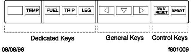
To reset a value, press the SET/RESET button twice.
Fig. 4.8, ICU4M/ICU2M Keypad
Main features of the ICU4M include:
Gauges that sweep 270 degrees and have pointers lit by an LED.
Service intervals that are programmable via two dash-mounted switches.
An audible warning and alert message to warn the driver if the door is opened without first setting the parking brake.
A flashing alert message that appears on the driver message center in low engine oil pressure or high coolant temperature conditions.
With the parking brake off, only the odometer and alert screens will display. Park the vehicle and set the parking brake to access additional screens.
The dash message center displays alert screens when certain conditions occur. They are warnings, cautions, or other messages that require the driver's attention, but not all of them are critical to the operation of the vehicle. Warning messages always display at full brightness.
More important messages take priority over less important messages. The order of priority is:
1.
parking brake set (with the vehicle moving)
2.
parking brake off (with the door open)
3.
low oil pressure or high coolant temperature
4.
hard brake warnings (if equipped with roll stability advisor)
5.
low battery voltage
6.
turn signal on
7.
service warnings
8.
no datalink activity
Alert Screens
NOTE: If there is more than one alert message to display, tap any key to access the next message, and so on, until all the messages have been viewed.
Parking Brake On
This warning message and an audible warning come on whenever the parking brake is applied and the vehicle is moving faster than 2 mph (3 km/h). The screen and audible warning go away only when the parking brake is released, or speed is reduced below 2 mph.
Low Oil Pressure
This warning message and an audible warning come on whenever the oil pressure falls below the minimum oil pressure, whether the vehicle is idling or in motion. Tap any key to dismiss the message.
If the fault is still active 30 seconds after the message is dismissed, the warning message will come on again.
High Coolant Temp
This message and an audible warning come on whenever the engine coolant temperature exceeds the maximum allowable temperature.
If the fault is still active 30 seconds after the message is dismissed, the warning message will come on again.
Low Voltage
On some vehicles, this optional message and an audible warning come on whenever the ICU detects a low voltage condition.
Turn Signal On
This warning message and audible warning come on whenever the turn signal remains on for four minutes or five miles of travel.
To dismiss this message, either turn off the turn signal or tap any key.
Service Warnings
Service warning screens display during the ignition sequence and indicate that a service interval has been reached or exceeded and maintenance is required. The messages may indicate the number of miles (KM) or hours until the next required service or, once passed, the number of miles (KM) or hours ago that maintenance should have been performed.
Automated Transmission Display
The ICU4M can display current gear information for vehicles with an automated transmission. The last three digits at the far right on the lower line of the driver display screen are reserved for this information.
If there is a request to shift, an up or down arrow is also displayed, depending on the shift direction.
On vehicles with conventional manual or automatic transmissions, the gear and shift direction are not displayed. For more information about specific models of automated transmissions, see Chapter 8 .
Mobile Screens
The following screens are available when the parking brake is off (when the vehicle is mobile).
Fasten seat belt (rpm<100)
Fuel economy (rpm>100)
Odometer
Trip distance/hours
Trip advisory
Leg distance/hours
Leg advisory
Outside air temperature
Fuel used/average MPG (KM/L)

Fig. 4.9, ICU4M Trip Information Screens
Stationary Screens
NOTE: Metric unit screens are similar. AMT= Current gear information for automated manual transmissions.
The following screens are available when the parking brake is on (when the vehicle is stationary).
Odometer
Trip information including trip miles/hours, idle hours, average speed, leg miles/hours
Fuel information including fuel used, fuel economy, idle/PTO fuel usage
Engine information including engine miles/hours, engine/PTO gallons, oil level
Diagnostic information
Service information including mileage or time to next service
Setup information
Vehicle information including Datalink status, ICU serial number, software version
Fasten seat belt warning
Trip Information
When idle hours are displayed, tap the any key to access the main trip information screen. See Fig. 4.9 . Tap the arrow keys on the 10-key keypad to advance through the screens. Press and hold the SET/RESET key to reset any of the screens.
Fuel Information
Fuel information allows you to view total fuel usage since the last reset, fuel mileage, and fuel consumed while idling or running the PTO. See Fig. 4.10 . Tap the arrow keys on the 10-key keypad to advance through the screens. Press and hold the SET/RESET key to reset any of the screens.
Engine Information
The engine information screens allow you to view engine mileage and hours, and total fuel consumption. See Fig. 4.11 . Tap the arrow keys on the 10-key keypad to advance through the screens.

Fig. 4.10, ICU4M Fuel Information Screens

Fig. 4.11, ICU4M Engine Information Screens

Fig. 4.12, ICU4M Diagnostic Information Screens
Press and hold the SET/RESET key to reset any of the screens.
Diagnostic Information
If active fault codes are displayed on the diagnostic information screens, make a note of the fault code and text message, then take the vehicle to an authorized Freightliner service facility as soon as possible. See Fig. 4.12 for a diagram of the diagnostic information screens.
Service Information
Service information allows you to view the next recurring service interval, expressed in either miles or hours. See Fig. 4.13 . Service intervals can also be deactivated, so they do not display at all.

NOTE: Service information screens only appear if the service interval is set to MILES or HOURS in Setup Information.
Fig. 4.13, ICU4M Service Information Screens
For programming service intervals, see Setup Information , below.
NOTE: If the vehicle has gone past the service interval, the miles (km)/hours remaining screen is replaced by the service was due screen, followed by the number of miles(km)/hours since the service was due.
Setup Information

Fig. 4.14, ICU4M Setup Information Screens (for service intervals)

Fig. 4.15, Other Setup Information
Setup information allows you to program various features of the ICU4M environment, including:
Service intervals (OFF/MILES/HOURS);
Target MPG;
LCD Lamp (ON/OFF);
Driver message center brightness;
Language (English/French/Spanish);
Units of measurement (English/Metric);
Driver select (ON/OFF)
Reset parameters to original settings.
Vehicle Information Screens
The vehicle information screens display hardware and software information, including the Freightliner part number and switch ID of the ICU. See Fig. 4.16 .

Fig. 4.16, ICU4M Vehicle Information Screens
ICU3
A mode/reset button, located on the right side of the ICU instrument cluster, is used to control the driver message center. See Fig. 4.2 . Tap the mode/reset button to advance one screen; press and hold the button to select a menu choice or reset the display. When the display resets, an audible chirp sounds.
Only four screens are accessible when the parking brake is off (mobile screens). All screens are accessible when the parking brake is on (stationary screens).
Mobile Screens
The following screens are available when the parking brake is off (when the vehicle is mobile) and no active fault codes are found. Tap the mode/reset button to scroll through the mobile screens.
Odometer
Trip distance
Trip hours
Back to odometer
Stationary Screens
The following screens are available when the parking brake is on (when the vehicle is stationary) and no active fault codes are found. Tap the mode/reset button to scroll through the stationary screens. See Fig. 4.17 .
Odometer
Trip distance
Trip hours
Select units
Diagnostics
Clear screen (on vehicles with less than 255 miles on the odometer)

Note: The engine oil level screen displays for Mercedes-Benz engines only (if equipped and enabled).
Fig. 4.17, ICU3 Stationary Screens
Engine miles
Engine hours
Engine oil level
Setup
Back to odometer
Trip Distance
When the odometer reading is displayed, tap the mode/reset button once for trip distance. Press and hold the mode/reset button to reset trip miles to zero.
Trip Hours
When trip distance is displayed, tap the mode/reset button once for trip hours. Press and hold the mode/reset button to reset trip hours to zero.
Diagnostic Information
When the DIAG screen is displayed, press and hold the mode/reset button to access the various diagnostic screens.
Trained technicians use the diagnostic screens to retrieve fault codes and other diagnostic information pertaining to the vehicle. If active fault codes display during start-up or at any other time, make a note of the fault code and take the vehicle to an authorized Freightliner service facility as soon as possible.
If fault codes are displayed, press and hold the mode/reset button to view the next fault code until reaching the DIAG screen.
If service intervals are enabled and service distance or time has been exceeded, the text SERVICE HOUR/MI (KM) will display at start-up to indicate vehicle service is required.
Engine Information
When the DIAG screen is displayed, tap the mode/reset button once to access the engine miles/hours screen. When the engine miles/hours screen is displayed, press and hold the mode/reset button to access the engines screen sub-menu.
Setup Information
The setup screen allows the driver to manage ICU parameters. When the engine hours/miles screen is displayed, tap the mode/reset button to access the setup screen. The setup screen submenu allows the driver to enable and change service intervals.
For each parameter, press and hold the mode/reset button to navigate to the parameter change screen. In each change screen, tap the mode/reset button to toggle between options.
When the setup screen is displayed again, tap the mode/reset button to view the odometer.
ICU2M
A keypad located on the auxiliary dash panel controls the driver message center. See Fig. 4.8 . The 10-key keypad is used to:
call up information on mobile screens;
navigate from screen to screen;
set up the display;
record significant data.
The odometer is a seven-digit display with one decimal point after the sixth digit, allowing it to display tenths of miles (or kilometers). When first installed, the odometer starts at 0.0 miles (or kilometers). When replaced, the odometer starts again from 0.0.
Alert Screens
Alert screens can appear at any time, even when the vehicle is moving. They override the regular screen display. They are warnings, cautions, or other messages that require the driver's attention, but not all of them are critical to the operation of the vehicle. The word Warning or Alert sometimes flashes on the display screen above the alert text. More important messages take priority over less important messages.
NOTE: If there is more than one alert message to display, press any button to scroll to the next message, and so on until all the messages have been viewed.
Parking Brake On
This warning message and an audible warning come on whenever the parking brake is applied and the vehicle is moving faster than 2 mph (3 km/h). The screen and audible warning go away only when the parking brake is released, or speed is reduced below 2 mph (3 km/h).
Low Oil Pressure
NOTE: All alert screens follow Low Oil Pressure alert format.
This warning message and an audible warning come on whenever the oil pressure falls below the minimum oil pressure, whether the vehicle is idling or in motion. See Fig. 4.18 . To dismiss the message, press any button on the keypad.

NOTE: All Alert Screens follow this format.
Fig. 4.18, ICU2M Alert Screen: Low Oil Pressure
If low oil pressure is detected during the ignition sequence, it displays as an active fault and the alert screen does not appear. After 30 seconds, this message displays again.
Low Coolant Level
This warning message and audible warning activate whenever the coolant level falls below a preset point.
High Coolant Temp
This message and an audible warning come on whenever the engine coolant temperature exceeds the maximum allowable temperature.
If high coolant temperature is detected during the ignition sequence, it displays as an active fault and the alert screen does not appear. After 30 seconds, this message displays again.
Low Voltage
On some vehicles, this optional message and an audible warning come on whenever the ICU detects a low voltage condition.
Faulty Speedo Gauge
This message is displayed when the system detects a faulty speedometer. This becomes the default screen, and vehicle speed is displayed as a digital readout at the bottom left of the screen. All other screens and functions operate normally.
Recirc Mode Engaged/Provide Fresh Air
The Recirc Mode Engaged message appears whenever recirculated air is selected on the fresh/air recirculation switch or the air circulation switch is rotated to the maximum air conditioning position. It displays one time only for seven seconds. It notifies the driver that recirculated air is being used and that fresh air needs to be provided after 20 minutes.
If fresh air is not provided after 20 minutes, Provide Fresh Air is displayed. It displays for seven seconds approximately every four minutes until the driver selects fresh air on the fresh/air recirculation switch or rotates the air circulation switch away from maximum air conditioning. See Chapter 4 for detailed operating instructions for the heater/air conditioner.
Low Fuel Level
The ICU continuously monitors fuel level. When the fuel level drops to 1/8th full, the word Warning flashes on the message display screen above the low fuel alert.
Turn Signal On
This message (the audible warning is optional) appears whenever the turn signal remains on beyond a preset time or distance traveled.
To dismiss this message, either turn off the turn signal or press any button on the keypad.
Service Warnings
Service warning screens display during the ignition sequence and indicate that a service interval has been reached or exceeded and maintenance is required. The messages may indicate the number of miles (KM) or hours until the next required service or, once passed, the number of miles (KM) or hours ago that maintenance should have been performed. The ICU2M can be programmed using ServiceLink to generate service warnings in either miles or hours, but not both.
No Datalink Activity
This message appears whenever the datalink is not receiving data. If the condition persists, take the vehicle in for service as soon as possible to discover the cause of the problem.
Mobile Screens
The following screens are available when the parking brake is off (when the vehicle is mobile) and no active fault codes are found. Press the appropriate button on the keypad to display one of the mobile screens.
trip miles and hours
fuel used and average MPG
leg miles and hours
NOTE: Resetting trip miles and hours also resets leg miles and hours.
To reset a mobile screen, push the Set/Reset button twice within a 6-second period while the screen is displayed. A confirmation screen will display after you press the button once.
NOTE: If the memory in the data logger is full, the screen will display Memory Full Data Not Recorded . If the data logger is not connected or not responding, the screen will display Data Recorder Not Responding . If the EVENT button was pressed within the last two minutes, the screen will display Still Recording Last Event .
Stationary Screens
The following screens are available when the parking brake is applied (vehicle is stationary) and no active fault codes are found. Each set of stationary screens has a title screen followed by one or more data screens.
To move forward and backward through these screens, use the three arrow buttons on the keypad. See Fig. 4.19 , Fig. 4.20 , and Fig. 4.21 for stationary screen navigation.
Trip Information: miles, hours
Fuel information: fuel used, average MPG

Fig. 4.19, ICU2M Engine Information and Diagnostic Information

Fig. 4.20, ICU2M Setup Information and Vehicle Information

Fig. 4.21, ICU2M Trip Information, Fuel Information, and Engine Information
Engine information: engine miles and hours, engine gallons and PTO gallons
Diagnostic information: active faults, historical dash faults
Setup Information: target MPG, brightness, language, units of measurement
Vehicle information: datalink activity/status, ICU part number, software ID number
Overhead Instrument Panel
The optional overhead instrument panel may hold a citizen's band (C/B) radio, digital clock, storage pocket areas for sunglasses and maps, and a locked glove box.
The underside of the overhead console also holds the sun visors and the optional dome/reading light assembly. See Chapter 5 for more information on the dome/reading light assembly.