Menu Structure
The OptiView instrument panel is an interactive graphical display that is capable of displaying text messages and graphics to communicate information about the status and performance of the vehicle to the operator. This information is organized in a menu-structured format around the following menu screens:
-
Gauges (Additional)
-
Steering Effort
-
Fuel Economy
-
Mobileye®
-
RoadWATCH™
-
Tire Pressure
-
Trip 1
-
Trip 2
-
Vehicle Settings
-
Diagnostics
The menus appear in the center of the instrument panel as shown in Fig.. When the instrument panel displays a message to the operator, it appears in the menu area.
Menu Navigation
Navigating through the system menus is done with the buttons on the left side of the steering wheel. See Fig.. Press the menu up or menu down arrows to highlight a menu, then press the OK button to enter the highlighted menu. Press the 'back' button to go back to the last menu that was displayed. Pressing the menu cycle button displays the next menu options with each button press. Press the 'home' button to return to the menus in their original order.
Gauge Menus
The driver can choose to display up to three gauge menus in the menu area if desired. See Fig., see Fig., and see Fig.. From the main menu, select 'Gauges' and press the OK button. Use the 'down' arrow to highlight one of the three currently viewed gauges, then press the OK button and the highlight will flash. Use the 'up' and 'down' arrows to scroll through the available gauges. Once you have selected the gauge to view, press the OK button again. The highlight stops flashing and that gauge is set. Use the same process to change the other two gauge menus.
Steering Effort
To adjust the steering wheel sensitivity, use the 'down' arrow on the steering wheel to select 'Steering Effort' and press OK. See Fig. , for an example of the steering effort menu. The driver can adjust the steering wheel sensitivity by pressing the up arrow on the steering wheel for more (more effort is required to steer) and the down arrow on the steering wheel for less (less effort is required to steer). The default sensitivity is set at 3.5. The steering sensitivity adjusts and is saved by the system in real time to allow the driver to feel the result of the changes. Press the back button to display the main menu.
Fuel Economy Menu
From the main menu, select 'Fuel Economy' and press the OK button. See Fig., for an example of the fuel economy menu.
Overall fuel economy is represented as a bar gauge while the red pointer indicates instantaneous fuel economy.
Press and hold the OK button to reset the distance to empty value and the average miles per gallon/kilometers per liter.
Mobileye®
Mobileye is a safety system available on some vehicles. The following information describes the various Mobileye features and whether or not the feature can be deactivated. For features that can be deactivated, use the 'down' arrow to select the applicable item for deactivation. See Fig., see Fig., see Fig., see Fig., see Fig., and see Fig..
Headway Warning Distance
Intelligent High-Beams (can be deactivated)
Lane Departure Warning (can be deactivated)
Pedestrian Warning
Speed Limit Indicator and Alert (can be deactivated)
Headway Warning Distance
When a vehicle is detected within a predefined headway (distance), the forward collision icon displays continuously below the numeric speedometer. See Fig.. If dynamic content is active in the center of the instrument panel, the indicator will be relocated to the bottom of the speedometer gauge. See Fig.. If a lead vehicle is detected, the green headway indicator is displayed and shows the headway time to the lead vehicle. When a lead vehicle’s headway is close, the headway icon will change to red and provide an audible chime. If the lead vehicle is breaking/approaching, the headway icon enlarges and an audible chime alerts the driver. See Fig..
Intelligent High-Beam Control
Note: The left-hand stalk switch must be in the high-beam position in order for the intelligent high-beam option to work.
When intelligent high-beam control is enabled and the vehicle is traveling faster than 21 mph (34 km/h), the high-beam headlamps automatically activate and deactivate on dark roads when there is no nearby traffic. The high-beam icon appears blue in the instrument panel when enabled and active; the icon is grey when the intelligent high-beam control is enabled but inactive. See Fig.. The driver can choose to deactivate this feature in the 'Intelligent High-Beams' menu. See Fig..
The icon is blue when the intelligent high-beam control is enabled and active; the icon is grey with an 'A' in the center when the intelligent high-beam control is enabled but inactive. A green icon indicates the low-beam headlamps are on.
Lane Departure Warning
An amber lane marker and assistance graphic appears in the center of the instrument panel when the vehicle unintentionally departs (with no turn signal) from the driving lane while traveling over 40 mph (64 km/h). The lane markings appear amber on the side the vehicle is veering toward. See Fig.. The driver can choose to deactivate this feature in the 'Lane Departure Warning' menu.
Pedestrian Collision Warning
The pedestrian collision warning is operational during daylight hours when the vehicle is traveling less than 31 mph (50 km/h). It alerts the driver with a red flashing icon and series of beeps when a pedestrian crosses in front of the vehicles path. A green icon activates when a pedestrian is detected in the danger zone but the time to collision is not critical. See Fig..
Speed Limit Indicator and Alert
If detected, a speed limit sign is shown continuously under the numeric speedometer reading. See Fig.. The speed limit indicator displays the last detected speed limit sign. If the over-speed threshold has been exceeded, the speed limit indicator flashes on and off. If speed limit data is not available, the speed limit indicator is not active. The driver can choose to deactivate this feature in the 'Speed Limit Indicator & Alert' menu. See Fig..
RoadWATCH™
Note: Standard cruise control is always available, however to use adaptive cruise control, the driver must select one of the three preset distance options. See Fig..
See Fig. for the cruise control menu location.
Standard Cruise Control
Standard cruise control automatically maintains a desired vehicle speed. Use the cruise control set button on the steering wheel once a desired speed is reached. Pressing the brake pedal or switching the cruise control button to OFF deactivates the system.
Adaptive Cruise Control
Adaptive cruise control uses radar to detect vehicles ahead and automatically adjusts the vehicle speed to maintain a safe distance.
When another vehicle is detected, a car appears at the top of the driver display screen along with the speed, distance and estimated time to reach that vehicle. See Fig.. As the other vehicle gets within a set distance, it is highlighted yellow to signal a warning range, and then highlighted red to signal a danger range.
An alarm also activates to notify the driver of the distance between the two vehicles. The driver can select the distance—far, near, or close—when the alarm is triggered. See Fig..
To use adaptive cruise control, use the down arrow on the steering wheel to select 'Cruise Control' from the main menu. Then use the down arrow on the steering wheel to select the alarm distance. See Fig., items 2, 3, and 4. The adaptive cruise control indicator activates in the instrument panel and 'Use Standard CC' appears in the display below the alarm distance options. If the driver wants to use standard cruise control, they can select 'Use Standard CC' from the cruise control menu.
Trip Menus
From the main menu, highlight 'Trip 1' and press the OK button. The TRIP 1 information appears on the screen. See Fig.. Press the 'down' arrow to view the bottom three items in the TRIP 1 screen. To reset the TRIP 1 information, press and hold the OK button.
The Trip 2 menu functions the same way after highlighting 'Trip 2' and pressing the OK button. See Fig.. To reset the TRIP 2 information, press and hold the OK button.
Tire Pressure Menu
The driver can select tire pressure from the main menu and quickly check tire pressure and temperature. A tire status of OK, LOW, HIGH, or LEAK appears. See Fig..
When tire pressure is selected, an overhead view of the vehicle is displayed with the tire pressure and temperature indicated for each tire; the tire pressure appears in bold above the temperature reading. Tires within a normal pressure range are white. Tires with low or high pressure or a tire with a leak detected are yellow. See Fig.. When the tire pressure monitoring system (TPMS) detects a tow vehicle, the number of tire sensors detected represents its graphic representation. See Fig..
Tire Warning
Vehicles equipped with a TPMS display a warning screen when a fault is detected. An overhead view of the vehicle is shown along with the tire pressure and temperature of each tire and a message—LOW PRESSURE, HIGH PRESSURE, or LEAK DETECTED—at the bottom of the driver display screen. See Fig.. To exit the tire warning screen, press the OK button on the left side of the steering wheel.
Vehicle Settings Menu
Selecting 'Vehicle Settings' from the main menu allows the driver to change system settings for bluetooth, dash brightness, fob programming, TPMS, units of measurement, and reset to default. See Fig..
Bluetooth
The bluetooth menu is used to connect devices, change the priority of connected devices, and remove a device's connectivity permissions. To set up a device, use the 'down' arrow to select 'Vehicle Settings', then 'Bluetooth' and press OK.
From the bluetooth menu, shown in Fig., choose 'Pair Device.' The information center searches for available devices. See Fig.. When devices are found, the driver can choose which one they want to pair with the information center. Once device pairing is confirmed, press OK on the steering wheel to exit back to the bluetooth menu.
Once a device is paired with the information center, incoming phone calls appear in the center of the display screen. See Fig.and see Fig.. The driver can accept or decline the incoming call using the phone controls on the steering wheel.
Call status appears in the top left of the display screen while a call is active and shows the call time, shown in Fig., or just after a call ends with a 'call ended' message.
Dash Brightness
To change the dash brightness, use the 'down' arrow to select 'Vehicle Settings', then 'Dash Brightness' and press OK. Press the up arrow on the steering wheel to increase dash brightness or the down arrow to decrease it. See Fig..
Fob Programming
To reset the fob programming, use the 'down' arrow to select 'Vehicle Settings,' then 'Fob Programming' and press OK. Use the 'up' arrow to select enable and the 'down' arrow to select disable. See Fig.. For additional key fob information, see Standard Ignition and Key.
TPMS Calibration
The park brake must be set before the system will allow the TPMS values to be updated. A message appears in the upper center over the RV graphic. See Fig.. Once the park brake is set, the message disappears and is replaced by the 'Hold OK to set TPMS values' message. See Fig..
Units of Measurement
After selecting 'Vehicle Settings,' then 'Units of Measurement,' the driver can choose standard or metric. See Fig..
Diagnostics
Selecting 'Diagnostics' from the main menu allows the driver to access the following sub-menus—Faults, Internal Diagnostics, Transmission Prognostics, System Information, and Radar Alignment. See Fig..
Faults
The Faults sub-menu, shown in Fig., displays the following faults should they occur:
-
antilock brake system
-
air pressure module
-
engine
-
instrumentation
-
transmission
Press the OK button to view any active faults.
Internal Diagnostics
The Internal Diagnostics sub-menu, shown in Fig., displays internal diagnostic information with the current value from the OptiView instrument panel.
Transmission Prognostics
The Transmission Prognostics sub-menu, see Fig., displays the following information:
-
oil level
-
oil filter
-
oil life
System Information
Selecting the System Information sub-menu, shown in Fig., displays the current system software version.
Radar Alignment
The Radar Alignment sub-menu, shown in Fig., displays the radar alignment percentage of completion.
Vision System Fault
Low visibility, no communication, temperature, and error codes from the Mobileye system activate a vision system fault message in the center of the instrument panel.
Vision System Communication Failure
When the Mobileye system experiences a communication failure, a message appears in the center of the instrument panel.
Automatic Traction Control
The automatic traction control system automatically limits wheel spin during reduced-traction situations. ATC applies gentle braking to the spinning wheel, to improve power to the wheel(s) with better traction. If both wheels are spinning, the system will signal the engine to reduce power.
Menu Off
If the driver selects menu off, the menu items no longer appear on the driver display screen. To view the menu items once again, press any of the arrows or the OK button on the left side of the steering wheel.

-
Tachometer
-
Engine Oil Pressure Gauge
-
Menu and Driver Message Area
-
Speedometer
-
Primary Air Pressure Gauge
-
Secondary Air Pressure Gauge
-
Low Battery Voltage Warning
-
Diesel Exhaust Fluid (DEF) Level Gauge
-
Fuel Level Gauge
-
Odometer
-
Coolant Temperature Gauge
-
Gear Shift Position Indicator
Fig. 1, Typical Instrument Panel, EPA10 and Newer Engines

-
Economy Mode Indicator
-
Service Soon
-
Steerable Tag Axle Warning
-
Malfunction Indicator Lamp (MIL)
-
Check Engine Warning
-
Left-Turn Indicator
-
Stop Engine Warning
-
Right-Turn Indicator
-
Parking Brake On Warning
-
Air Brake Warning
-
Adaptive Cruise Control Indicator
-
Fasten Seat Belt Warning
-
Wait to Start Indicator
-
Pedestrian Collision Warning
-
Low Windshield Washer Fluid Indicator
-
Marker Light Indicator
-
Automatic Traction Control Indicator
-
Headlight/High-Beam/Automatic High-Beam Indicator
-
Fog Lamp Indicator
-
Electronic Stability Control (ESC) Indicator
-
Tire Pressure Monitoring System Indicator
-
Forward Collision System Indicator
-
Lane Departure Warning
-
Low Battery Voltage Warning
-
Low Secondary Air Pressure Warning
-
Engine RPM
-
Cruise Control Indicator
-
Low Primary Air Pressure Warning
-
Speed Limit Indicator
-
Forward Collision Warning
-
Low Diesel Exhaust Fluid (DEF) Warning
-
Low Fuel Indicator
-
Water in Fuel Indicator
-
Low Oil Pressure Warning
-
Diesel Particulate Filter (DPF) Lamp
-
High Exhaust System Temperature (HEST) Lamp
-
High Coolant Temperature Warning
-
Shift Inhibit Indicator
-
Service Transmission Indicator
-
Transmission Overheat Warning
-
Transmission Warning
-
ABS Warning
-
Engine Brake Indicator
-
Bluetooth Smartphone Indicator
Fig. 2, Warning Lamps, EPA10 and Newer Engines

Fig. 3, Standard Automatic Transmission Mode (drive indicator shown)

-
A message appears briefly to indicate the transmission mode.
Fig. 4, Transmission Mode Message

Fig. 5, Gear Position Indicator (shown during engine braking)

-
Engine Brake Indicator
Fig. 6, Engine Brake Engaged

Fig. 7, Menu Screen

-
Cruise Accelerate/Resume
-
Marker Interrupt
-
Cruise Decelerate/Set
-
Phone Hang-Up/Reject
-
Mute Button
-
Phone Pick-Up
-
Cruise On/Off
-
Cruise Cancel
-
Volume Increment Up
-
Back Button
-
Volume Increment Down
-
Menu Down
-
Menu Cycle
-
Home Button
-
OK Button
-
Menu Up
Fig. 8, Steering-Wheel-Mounted Switches

-
Transmission Temperature and Turbo Boost
Fig. 9, Gauge Menus, Option 1

-
Oil Pressure and Coolant Temperature
Fig. 10, Gauge Menus, Option 2

-
Engine Load and Gear
Fig. 11, Gauge Menus, Option 3

Note: The default sensitivity is set at 3.5.
Fig. 12, Steering Effort Menu

Fig. 13, Fuel Economy Menu

Fig. 14, Mobileye Menu

Fig. 15, Headway Warning Distance Menu

Fig. 16, Intelligent High-Beams Menu

Fig. 17, Lane Departure Warning Menu

Fig. 18, Pedestrian Warning Menu

Fig. 19, Speed Limit Indicator and Alert Menu

-
Headway Warning Distance Indicator
-
Speed Limit Indicator
Fig. 20, Headway Warning Distance and Speed Limit Indicator

-
Headway and Speed Limit Indicators
Fig. 21, Relocated Headway and Speed Limit Indicator

Fig. 22, Headway Icon Enlarges

-
The lane markings appear amber and a vehicle image is shown veering toward the appropriate lane, either left or right, of departure.
-
Lane departure warning telltale displayed.
Fig. 23, Lane Departure Warning

-
Standard cruise control is selected. There is no headway protection (adaptive cruise control) provided when standard cruise control is used.
-
Cruise Control Indicator
Fig. 24, Cruise Control Menu, Standard Cruise Control Screen Shown

-
The car image can be highlighted yellow (warning range) or red (danger range). The speed, distance and estimated time to reach the other vehicle are also provided to the driver.
-
Adaptive Cruise Control Icon
-
Alarm Distance, Close
-
Alarm Distance, Near
-
Alarm Distance, Far
Fig. 25, Adaptive Cruise Control Screen

Fig. 26, TRIP 1 Information

Fig. 27, TRIP 2 Information

-
The tire pressure and temperature of each tire are shown.
-
TPMS system detects a tow vehicle.
Fig. 28, Tire Pressure Screen

-
Tow vehicle tire pressure and temperature of each tire shown.
Fig. 29, Tow Vehicle Tire Pressure Screen

-
The tire warning screen indicates that one tire has low pressure, indicated by the yellow tire and pressure reading on the driver display screen.
-
Low tire pressure and high tire temperature detected.
Fig. 30, Tire Warning Screen

Fig. 31, Vehicle Settings Menu

Fig. 32, Bluetooth Menu

-
The information center searches for available devices.
-
Select the device to pair with the information center.
-
The information center and device are connecting.
-
A message tells the driver a device is paired.
Fig. 33, Bluetooth Pairing

-
Incoming Call Status Shown
Fig. 34, Incoming Call Status Screen

Fig. 35, Incoming Call With Contact Photo

Fig. 36, Dash Brightness

Fig. 37, Fob Programming

Fig. 38, Set Park Brake to Calibrate TPMS Screen

Fig. 39, Set TPMS Values Screen
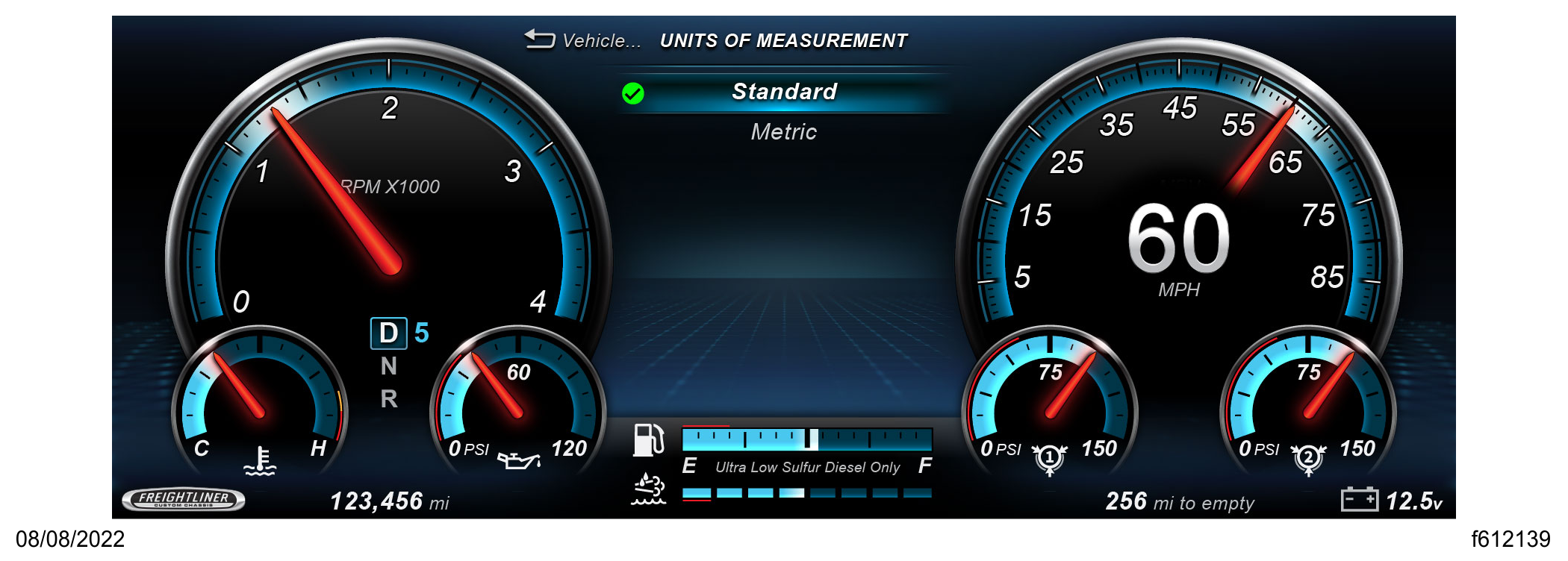
Fig. 40, Units of Measurement

Fig. 41, Diagnostics Sub-Menu

-
Active Faults
Fig. 42, Faults Sub-Menu

-
Current Sub-Menu Values
Fig. 43, Internal Diagnostic Sub-Menu

-
Transmission Information
Fig. 44, Transmission Prognostics Sub-Menu

-
Software Version
Fig. 45, System Information Sub-Menu

-
Radar Alignment Percentage of Completion